Hi! Is there anything to know when adding headers to the holes at the back of the module? I want to connect it to the ES-9 with jumper wires inside the case so i can control the midi from a computer without extra cable cluther. I’m experienced with soldering so i’m not expecting any complications on that side. I don’t have the module yet, just looking at the possibilities.
Thanks!
The test points at the back of the module have a direct electrical connection to the jacks at the top.
Please note the header is 1.27mm pitch, rather than the very common 2.54mm.
- SP1, SP2, SP3, SP4 are the sample outputs (jack tip)
- M1, M2, M3, M4 are the ‘mix’ inputs. When no jack is plugged into the output of a sample, is is normalled to the internal mixer. These test points have a direct electrical connection to the jack socket “normal” pin. So be careful if you plan on using these, as they are by default shorted to their corresponding sample output.
- MIX is the mix output that you’d expect at the MIX jack.
- INPUT is an additional mixer input. By default, it is connected to nothing.
- M1, M2, M3, M4 and INPUT have an input impedance of 100KΩ
- MIDI IN ‘DATA’ and ‘+’ are connected as follows:
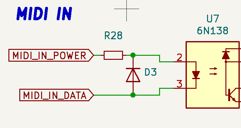
- Finally MIDI thru is just MIDI IN through a buffer IC.
Let me know if you have any more questions
Cheers
1 Like
Thanks for the detailed explanations, i think everything’s there!
This topic was automatically closed 21 days after the last reply. New replies are no longer allowed.